


First-time failure is usually not a product destiny problem. It is a boundary definition problem.
Test Systems
GtestWorks Automated Testing Platform
VectWorks 3.0 Electrical Performance Test Software



The biggest risk in EMC testing is not finding a problem. It is finding the problem only when the product is already in formal certification. Many teams end up in repeated rework not because the product is impossible to pass, but because the test environment, sample configuration, standards interpretation, and corrective-action loop were never made solid early enough. This page turns the most common EMC mistakes into a practical framework your R&D, test, and certification teams can use together.
If you only need the highlights, start with the FAQ, the seven critical stages, and the quick troubleshooting table. If you are building pre-compliance workflows, running corrective actions, or planning an EMC lab, continue through the six major failure zones, standards references, and Greentest solution section.
Teams usually do not get stuck in EMC because a design is fundamentally impossible. They get stuck because the activities that make test data trustworthy were pushed too late. Site conditions, standard boundaries, EUT operating modes, accessory consistency, corrective-action traceability, and retest closure are the six foundations. If any one of them is weak, the project quickly becomes noisy and inefficient.
First-time failure is usually not a product destiny problem. It is a boundary definition problem.
If modifications are not logged, retested, and compared, EMC work turns into noise.
The earlier high-risk frequencies and operating modes appear, the less painful formal testing becomes.
The goal is not luck. It is traceable, explainable, reusable EMC evidence.
EMC testing is not just about a single pass in a formal lab. It tests whether the team has organized standards selection, sample configuration, environment control, record keeping, and corrective-action rhythm into one engineering loop.
You can use it as a project kickoff risk list, a pre-compliance preparation sheet, a corrective-action review guide, or a training baseline for EMC lab planning and test process standardization.
The real danger in EMC is not seeing a limit exceedance. The real danger is seeing it for the first time when the product has already entered formal certification. Strong teams expose risk during development instead of turning certification into a diagnosis session.
These are the questions that teams keep revisiting. Clear them first and the later sections become much easier to apply.
In most cases, the product is not inherently hopeless. The preparation is incomplete. The site may be non-representative, the EUT operating mode may be unrealistic, cables and peripherals may be missing, or the standard may have been interpreted incorrectly. Any of these can distort the result and send the team in the wrong correction direction.
Because they never establish a clear loop. One day the cable routing changes, the next day a part changes, then a filter is added. If every change is not recorded, retested, and compared, the team loses visibility into what actually worked.
Yes, and the earlier the better. The purpose is not to get a formal conclusion in advance. The purpose is to expose high-risk frequencies and high-risk operating modes while the design is still flexible.
Because one passing sample does not guarantee production consistency. If margins are thin, cable layouts are hard to reproduce, or process tolerances are weak, later production lots can still fail in audits or customer environments.
You can borrow lessons, but you cannot copy conclusions. Each product category uses a different standards system, test set, operating state, and pass-fail logic. The applicable standard boundary has to be right first.
When several correction rounds still do not isolate the problem, when multiple standards overlap, when lab planning becomes difficult, or when certification timing starts affecting launch targets. At that point, structured capability is usually cheaper than continued blind trial-and-error.
These terms are often used loosely in real projects. Define them first so the rest of the discussion stays precise.
| Term | Definition |
|---|---|
| EMC | Electromagnetic Compatibility. The ability of equipment to operate properly in its intended electromagnetic environment without generating unacceptable interference to other equipment. |
| EUT / DUT | Equipment Under Test / Device Under Test. Both expressions are common in engineering practice. |
| CE | Conducted Emission. |
| RE | Radiated Emission. |
| EMS | Electromagnetic Susceptibility or Immunity. |
| Margin | The safety distance between a measured result and the applicable limit. Smaller margins usually mean higher consistency risk later. |
| Pre-Compliance | Pre-scan, pre-verification, or troubleshooting tests performed before formal certification or final validation. |
If time is short, at least run through this table. It helps determine whether the current risk is mainly coming from the site, standards, operating mode, accessories, or the correction method itself.
| Stage | Common Mistake | Direct Consequence | Recommended Action |
|---|---|---|---|
| Test Environment | Treating an ordinary shielded room as a compliant emission site | Results do not correlate with the formal lab | Confirm site type, grounding, chamber condition, and calibration validity against the target standard |
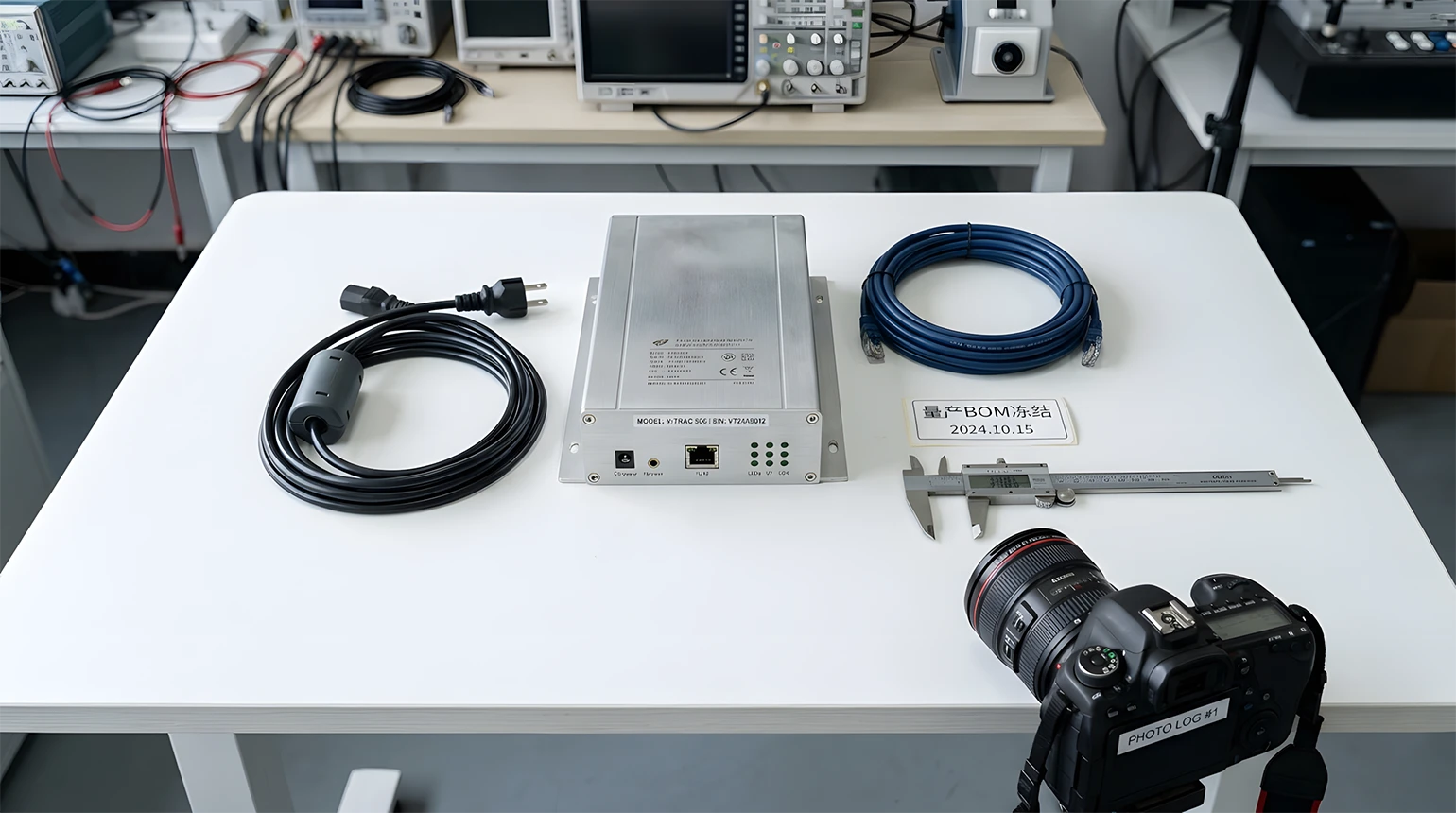
| Grounding and Setup | Changing grounding, wiring, and cable routes casually | Poor repeatability and weak fault isolation | Freeze the setup method and retain photos and setup records |
| Standard Selection | Choosing by product name only, not by use environment | Wrong limits, test items, or frequency range | Judge product category, port type, and use environment first |
| Instrument Parameters | Wrong detector, bandwidth, or scan strategy | Missed findings or false conclusions | Use standard-based templates and manually review key settings |
| Operating State | EUT not running in a representative mode | Results do not reflect the real risk | Define typical modes, loads, and port connection states clearly |
| Correction Method | Changing many things at once without comparison | No way to tell what actually helped | Change one key variable at a time and retest immediately |
| Production Transfer | Ignoring process or accessory changes after a prototype pass | Production consistency drifts out of control | Control critical accessories, cables, grounding, and configuration items formally |
Mature EMC work means organizing sites, standards, modes, accessories, corrections, and retests into one closed loop before the project gets trapped in last-minute pressure. The 13 problems below are different symptoms of the same missing control structure.
The first four pitfalls can distort the whole direction during pre-compliance. If the site is wrong, the grounding is unstable, the parameters are copied blindly, or the accessories do not match the task, later corrective actions may be built on invalid conclusions.
Many teams start in a place that looks like a lab, but EMC work depends on whether the site really matches the target method. In radiated emissions, for example, site type, floor structure, and absorber condition all affect whether pre-compliance data can correlate with the formal chamber.
Decide first whether the task is conducted emission, radiated emission, or immunity. Then confirm the site type against the standard, instead of only asking whether the room has shielding. Archive site checks, chamber calibration status, and equipment calibration records.
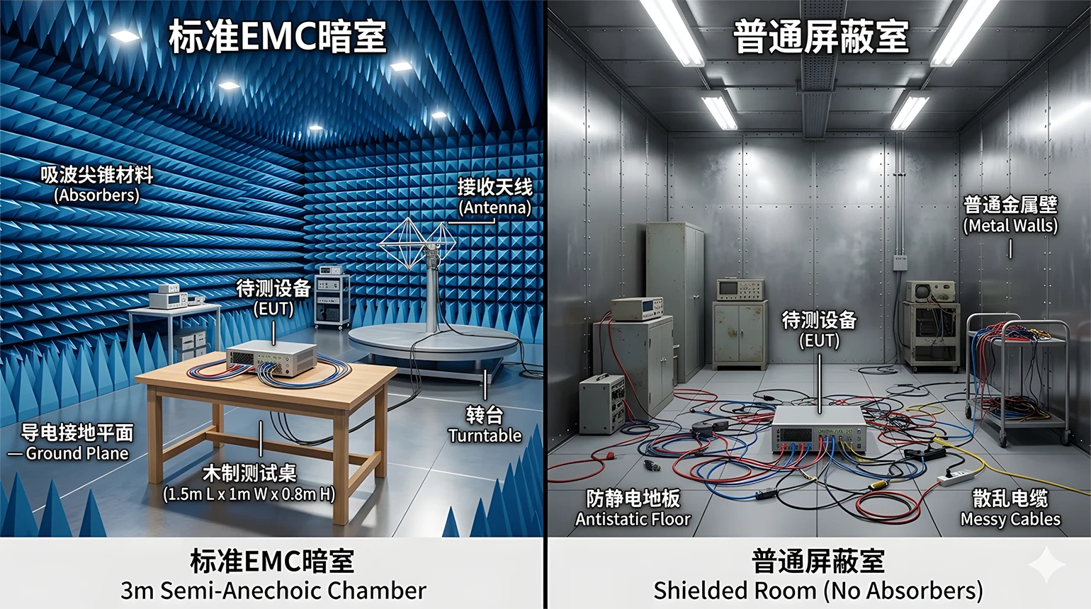
Greentest provides EMC test systems and chamber construction solutions covering EMI and EMS systems as well as laboratory planning, helping teams upgrade from temporary usability to long-term repeatability.
The real EMC nightmare is not one exceedance. It is the same sample giving different results after a setup change. The core issue is not applying a single numeric grounding rule. It is maintaining grounding continuity, low-impedance connection paths, layout consistency, and complete records.
Freeze grounding and layout methods based on the standard and lab work instruction. Keep photos of critical cable paths, grounding points, and auxiliary equipment positions. Keep pre-compliance and formal test configurations aligned as closely as possible.
Greentest can provide EMC system integration, lab planning, and standardized test-flow support so grounding topology, cable routing, accessory selection, and records stay under one management framework.
Wrong bandwidth, step size, dwell time, or detector mode can lead directly to missed findings or false conclusions. The dangerous case is not obvious failure. It is when the team believes the test was complete even though the setup was wrong.
Use target-standard templates for setup and manually review detector type, bandwidth, scan range, antenna or table strategy, and boundary frequencies. Do not rely on the first plot alone.
Greentest EtestWorks software can manage conducted emission, radiated emission, conducted immunity, and radiated immunity in one workflow, reducing parameter errors through reusable templates, automation, and structured result handling.
Antennas, LISNs, coupling clamps, current probes, and cable fixtures are not generic consumables. Wrong selection, expired calibration, or use outside the intended scenario undermines the credibility of the entire test result.
Confirm accessory coverage against target frequencies and test methods, verify calibration status and serial-number consistency, and record the key accessory list explicitly in the test log.
Greentest can support EMC system configuration and lab planning so teams build clearer matching logic between test item, frequency coverage, accessories, and equipment management, reducing rework caused by unsuitable fixtures.
Once the wrong standard is chosen, limits are treated too absolutely, the EUT is not in a representative state, or the test sample drifts away from production intent, every retest round can end up reinforcing the wrong boundary.
EMC is not “test first and find the standard later.” The valid sequence is “identify the correct standard boundary first, then design the test plan.” Product name alone is not enough. Product category, application scenario, port type, installation conditions, and customer requirements all matter.
Map the product sector, port types, use scenario, and installation method. Confirm the product standard, basic standards, method standards, and customer clauses together. For products used in more than one environment, decide early whether more than one test route is required.
Greentest can support standards interpretation, test-plan development, and lab-capability planning so the project defines category, compliance boundary, and verification path early instead of discovering the mistake after a full test round.
Statements such as “Class B is about 10 dB stricter than Class A” or “radiated tests usually stop at 1 GHz or 6 GHz” can be useful memory aids, but they are not engineering decisions. Different standards, products, and port structures do not always use the same upper limits or the same limit relationships.
Do not let verbal habit replace the actual clause. Use the latest effective version of the target standard for limit lines and frequency range. For high-speed ports, wireless functions, and vehicle interfaces, verify the upper frequency boundary carefully.
Greentest can combine EMC systems with standardized workflows to help engineering teams identify key frequency zones, key operating modes, and high-risk interfaces before formal testing begins.
This is one of the most common and least discussed EMC logic errors. If the EUT is not running in a representative mode, even a clean-looking report does not prove that real-world risk has been controlled.
Choose the mode that best represents risk, not the one that passes most easily. Define port states, accessory lists, load conditions, and software version. For multi-mode products, cover the few modes that actually matter most.
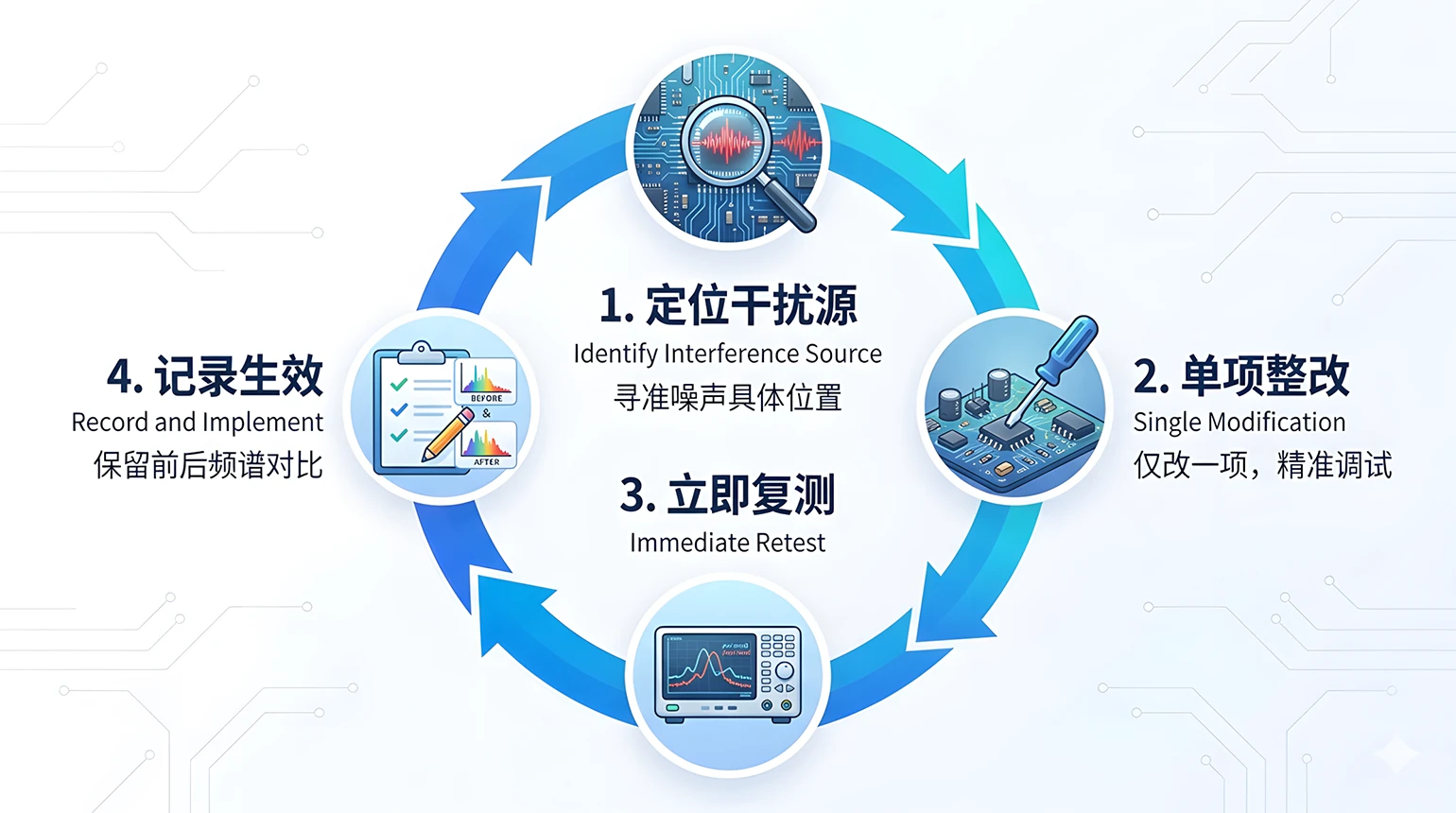
Greentest can support test-flow planning and automation so representative operating modes, port connection methods, load conditions, and state switching are managed in structured templates with better run-to-run comparability.
Many EMC issues do not start on the test day. They start later, when parts change, cables change, enclosures change, or adapters change. Once the tested sample no longer matches the actual production BOM and document set, the value of the test result drops rapidly.
Freeze the critical BOM, harnesses, shielding parts, grounding parts, and software version before the test. Include optional accessories and alternatives in the evaluation scope. When versions change, perform delta analysis or supplemental testing promptly.
Greentest can help teams establish test-configuration lists, sample-version records, and technical-data management so R&D, test, and certification functions stay aligned and late-stage retests are reduced.
| Reference Direction | Typical Standards | Use |
|---|---|---|
| Measurement Methods | CISPR 16 / GB/T 6113 series | Defines instrumentation, accessories, methods, and site requirements |
| Multimedia Equipment | CISPR 32 / GB/T 9254.1 | Used for multimedia emission requirements |
| Industrial, Scientific, and Medical Equipment | CISPR 11 / GB 4824 | Used for ISM emission requirements |
| Automotive Electronics | ISO 11452 / GB/T 17619 series | Used for vehicle component immunity assessment |
| Medical Devices | IEC 60601-1-2 / YY 9706.102 | Used for medical electrical equipment EMC compliance judgment |
The last five pitfalls look like execution details, but they are often what truly stretches the project. If the team cannot read margins, cannot control variables, cannot isolate root causes, does not prepare technical files, or uses formal certification as a diagnosis site, cost and schedule both expand quickly.
Looking only at pass or fail hides real production risk. Any frequency point sitting close to the limit should already be treated as a high-priority risk, even if it is technically inside the line today.
Build a high-risk frequency list instead of saving only a final screenshot. Compare spectral trends before and after modifications, not just the highest number. Include uncertainty, sample variation, and cable movement in the evaluation.
Measurement uncertainty should not be treated as one fixed threshold for every project. A safer approach is to check the current accredited scope, equipment capability, and project-specific uncertainty documents of the laboratory, then judge the result in context.
Greentest can combine EtestWorks with EMC test systems so key frequencies, before-and-after changes, and result history are logged and compared more systematically, improving troubleshooting speed and risk judgment.
The worst EMC correction habit is changing three or four things at once and then checking the result. Even if the spectrum improves, no durable knowledge is created. If it gets worse, the failure path becomes hard to reconstruct.
Change one major variable at a time, such as filtering, shielding, grounding, or routing. Retest immediately after each change and save the before-and-after data. Distinguish narrowband issues, broadband noise, common-mode paths, and differential-mode paths explicitly.
Greentest can support a one-change, one-test, one-comparison correction flow through automation and standardized test procedures, helping teams identify effective actions faster.
Experience can be useful, but it cannot replace diagnosis. Different products have different interference sources, coupling paths, and structural boundaries. Without fault isolation first, even a respected correction recipe may simply add a new round of trial cost.
Locate the interference source first, then choose the correction path. Use near-field scanning, frequency correlation, and structural review to form a root-cause hypothesis. Treat experience as a hypothesis and measurement as the conclusion.
Greentest can combine EMC platforms, solution planning, and engineering support so “experience-driven correction” becomes “location-driven correction,” making each test cycle more reusable.
EMC testing is never a standalone activity. If the manual, specification, schematics, block diagram, critical parts list, software version notes, or application materials are incomplete, certification rhythm slows down immediately.
Prepare one controlled technical package before the test. Define sample ID, hardware version, software version, and accessory list clearly, then align documentation expectations with the lab or certification body in advance.
Greentest can help sort sample information, configuration lists, and documentation requirements during solution planning and project execution so the interfaces between engineering, test, and certification stay cleaner.
The purpose of formal certification should be to verify design maturity, not to discover the basic EMC problem for the first time. If formal testing is used as pre-compliance, project duration, cost, and team pressure all expand together.
Finish basic pre-compliance and main risk screening during development, run at least one structured retest before submission, and keep before-and-after evidence for corrected high-risk frequencies.
Greentest can provide EMC systems, chamber planning, and test-strategy support that helps teams solve problems during development, not during the most expensive stage of the project.
Identify the source and coupling path before choosing filtering, shielding, grounding, or routing actions.
One change, one retest, one comparison is the shortest path to reusable knowledge.
Formal submission should verify maturity. Diagnosis belongs earlier in the development cycle.
When a project already shows a typical symptom, this table helps reverse-map the most likely investigation path before the team spreads effort too widely.
| Observed Symptom | Priority Check Direction | Suggested Action |
|---|---|---|
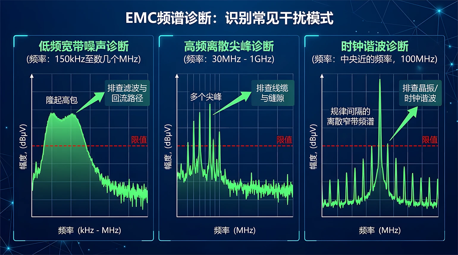
| High conducted noise from 150 kHz to several MHz | Switch-mode power input stage, common-mode and differential-mode filtering | Check switching frequency, filter topology, and return path |
| High radiated emissions from 30 MHz to 100 MHz | Cables, enclosure seams, grounding continuity | Inspect cable routing, shield connection, and chassis bonding |
| Strong discrete peaks at fixed frequencies | Crystal oscillators, clocks, switching-node harmonics | Run frequency correlation and inspect clock source and layout |
| One frequency improves while another gets worse after correction | Coupling path moved | Roll back, split the changes, and verify step by step |
| Large repeatability difference on the same sample | Layout, grounding, and operating state inconsistency | Freeze the configuration and recheck site and accessory condition |
| Category | Reference | Use |
|---|---|---|
| Test Methods | CISPR 16 series | Defines receivers, accessories, methods, and site requirements |
| Multimedia Equipment | CISPR 32, GB/T 9254.1 | Used for multimedia equipment emission assessment |
| ISM Equipment | CISPR 11, GB 4824 | Used for industrial, scientific, and medical equipment emission assessment |
| Automotive Electronics | ISO 11452, GB/T 17619 series | Used for vehicle component immunity assessment |
| Medical Devices | IEC 60601-1-2, YY 9706.102 | Used for medical electrical equipment EMC assessment |
The exact applicable standard must still be decided from product category, use environment, customer requirements, and the latest effective version. This table is only a direction guide, not a formal compliance decision.
Guided by the idea of being an engineer’s testing steward, Greentest provides one-stop solutions around electrical performance testing systems, EMC testing systems, automation platforms, and laboratory planning and construction.
| Item | Information |
|---|---|
| Company Name | Guangzhou Greentest Electronics Technology Co., Ltd. |
| Brand | Greentest |
| Founded | November 2015 |
| Positioning | Focused on electrical performance and EMC test solutions |
| Qualifications | National high-tech enterprise and specialized SME recognition |
| Concept | Engineer’s Testing Steward |
| Category | Product / Service | Typical Use |
|---|---|---|
| EMC Automation Platform | EtestWorks | Template-driven and closed-loop management for conducted emission, radiated emission, conducted immunity, and radiated immunity |
| Conducted Emission System | ES5501 Series | Conducted disturbance testing on power lines and signal lines |
| Radiated Emission System | ES5502 Series | Radiated disturbance testing above 30 MHz |
| Radiated Immunity System | ES5601 Series | RF radiated immunity testing |
| Laboratory Capability Build-Up | EMC systems and chamber construction | Enterprise lab planning, system integration, and site construction |
| Testing Steward Services | Standards interpretation, solution planning, training, qualification support | Helps teams reduce trial-and-error time and improve test organization efficiency |
The most common EMC pitfalls are usually not rare surprises. They are the basic actions teams quietly skip: confirming the site, choosing the correct standards boundary, defining representative operating modes, keeping accessories consistent, documenting corrections, and closing the retest loop. Real EMC strength comes from making each test repeatable, traceable, and reusable.